Wayne's World:
This is applicable to the Hitachi Distributor
model D6K8, D6K9, D6K80 and D6K81 part number 22100-P9101 found on a 1979 N/A
L28E.
Inside the distributor there is a part called a Breaker Plate Assembly, part
number 22136-Q1700. It is two metal plates that has a triangular plastic plate
with three ball bearing, one at each point of the triangle, sandwiched between
the two metal plates. The ball bearings keep the two plates apart.
The plastic triangle acts as a race to keep the ball bearings in place. The
bottom plate is fastened to the distributor housing. The top plate is connected
to the rod from the vacuum advance, part number 22301-N4700 (this number is for
reference ONLY, there are 12 different vacuum advance modules).
The Pickup Kit, part number 22229-Q1700, is fastened to the top plate of the
Breaker Plate Assembly. The Stator, part number 22163-Q1700, is placed on top of
the Magnet, part number 22158-S6700, and both units are fastened to the Pickup
Kit.
Finally, the Reluctor, part number 22115-Q1700, sits on the distributor shaft
and is held solidly in place with a pin. It is located mid-way between the Rotor
and the Mechanical Advance Mechanism.
There are six teeth on the Reluctor and six teeth on the Stator. Each time all
the teeth line up, the magnetic field, that is always being produced by the
magnet, is altered.
Each time the magnetic field collapses and expands it acts as an on / off switch
for the current flowing through the Pickup Kit.
The distance between the teeth on the Reluctor and the Stator is called the Air
Gap and should be between .006 and .016 inch. This should be measured with a
brass feeler gauge because of the magnet.
The Pickup Kit is the part that sends pulses to the Transistor Ignition Unit on
the outside of the distributor.
The operation of the Transistor Ignition Unit is outside the scope of what I am
trying to explain at the moment but it is basically an electronic filter and a
high current switch. The filter part takes the input from the Pickup Kit and
makes it into nice, clean, square waves. These square waves are sent to the high
current switch part which is connected to the (-) side of the ignition coil.
The Ignition Module for 1979 to 1981 is Nissan part # 22020-S6702 (aka E12-80).
The Ignition Module for 1982 and 1983 280ZX N/A (E12-92 Nissan # 22020-W3100 or
E12-93 Nissan # 22020-P9700)
Each time the high current switch closes there is current flow between the
battery and ground through the '+' and '-' terminals on the ignition coil.
Current flow in the Primary Side of the ignition coil induces a higher voltage
in the Secondary Side of the ignition coil.
The Secondary Side of the ignition coil now contains around 50,000 volts. When
the high current switch opens there is no current flow in the Primary Side of
the ignition coil and the Primary field collapses. The voltage stored in the
Secondary Side of the ignition coil now has to go somewhere.
When the rotor lines up with a tower in the Distributor Cap the voltage goes out
the high tension lead of the coil to the distributor, down the rotor, JUMPS to
the NEAREST spark plug wire post inside the distributor cap, down that wire to
the spark plug and then BOOM, an explosion in a cylinder.
Z'ed should go vrooom.
Way back, up in the beginning. I mentioned the Mechanical Advance Mechanism.
There are two key components of Mechanical Advance.
First is the AMOUNT of Mechanical Advance.
For the Hitachi distributors, this is completely controlled by the length of the
advance slot in the Cam Set (part number 22132-P7100). If you don't know where
these are, open up your distributor, take off the rotor, and look under the
Breaker Plate Assembly. Now force the weights out and look for where you see the
pin moving in the slot. Once you have seen this, it is pretty easy to understand
how to change the amount of advance. To get less, braze the slot so it is
shorter. If you want more advance, then lengthen the slot.
On the bar with the slot in it will be a number stamped into the metal. It will
be 8.5 or 9. These numbers correspond to the number of degrees that the rotor
will advance relative to the base of the shaft. Since the crankshaft rotates
twice each time the distributor rotates once simply multiply the number by two
to get the total mechanical advance.
The second component of Mechanical Advance is the Advance Curve.
The Advance Curve is controlled by the shape and weight of the weights, shape of
the cam (in between the weights) and the tension of the springs. If you install
lighter springs, the weights will be able to extend out at a lower RPM. If you
install heavier springs, it will take a higher RPM for the weights to overcome
the force of the springs.
Since the Stator is fixed to the Breaker Plate Assembly, which in turn is fixed
to the distributor body, and the Reluctor is fixed to the Cam Set, as the RPM
changes, the weights move, and changes the relationship of the Reluctor to the
Stator.
To check the mechanical advance:
Disconnect the vacuum advance hose and plug it with something.
Set the engine speed as close to 600 RPM as you can and note the timing. Now
increase the RPM to 2,500 and your timing should advance 17 degrees (if the Cam
Set has 8.5 stamped on it). I.E. If base timing is 10 degrees BTDC at 600 RPM it
should be 27 degrees BTDC at 2,500 RPM. (See Note at end)
Vacuum Advance is used to advance the spark as manifold vacuum is increased. It
should be noted that Vacuum Advance is primarily for Fuel Economy, and has no
affect on your performance at Wide Open Throttle (WOT), since you have almost no
vacuum present.
As engine vacuum changes the rod attached to the Breaker Plate Assembly moves
the top plate and changes the timing by moving the Stator.
To test if the mechanical part of the vacuum advance is working do the
following:
Remove the Distributor Cap.
Disconnect the Vacuum line at the Vacuum Advance unit.
Connect a vacuum pump to the Vacuum Advance Unit. As you apply vacuum the rod
should retract and the Stator should move. At around 10 - 15 inches of vacuum
the rod should be fully retracted and the vacuum should not change.
If the vacuum goes down there is a leak in the diaphragm and the Vacuum Advance
Unit will have to be changed. You have also just discovered the vacuum leak that
makes the engine run rich.
If the vacuum does not change, and the rod does not move, the Breaker Plate
Assembly needs service.
If you can see ball bearings in the bottom of the distributor you need a Breaker
Plate Assembly anyway.
When the loose bearings end up wedged in the counter - weights for the
mechanical advance that will stop working also.
To check the vacuum advance with the engine running:
Hook a vacuum pump to the vacuum advance unit. Slowly increase the vacuum to 6
inches and at this point engine RPM should start to increase and the timing
should start to advance. At 10 inches of vacuum you should have more than 10
degrees of vacuum advance. (See Note at end)
Just remember that as RPM increases when testing the vacuum advance the
mechanical advance will be kicking in also.
Now hook the vacuum line back up to the vacuum advance unit and increase the RPM
to above 2,500 RPM.
If you started off at 10 degrees you should now have 27 PLUS whatever you got
when you tested the vacuum advance. I.E. 10 + 17 + 10 = 37 degrees @ 2,500 RPM.
Notes:
The manner in which Nissan chose to list the Service Data Specifications for the
Mechanical / Vacuum Advance need explaining.
Centrifugal Advance:
[Distributor Degree / Distributor RPM]
0/600
8.5/1,250
If you have access to a Distributor Analyzer this means that at 600 distributor
shaft RPM you should have 0 degrees of mechanical advance, and at 1,250
distributor shaft RPM you should have 8.5 degrees of mechanical advance. All of
this is measured comparing the relative position of the rotor to the distributor
cap tower. Since it is not likely that we would have a $40,000.00 Distributor
Analyzer in the closet we need a more practical method to test this and that
would be a timing light. For each complete rotation of the distributor shaft the
Crankshaft has to turn twice.
So the S.D.S. has to be translated into Crankshaft relative information so that
it becomes:
[Crankshaft Degree / Crankshaft RPM]
0/1,200
17/2,500
You simply take the original numbers and multiply each one by 2 and now you use
the timing mark on the Damper Pulley.
This means that at 1,200 Crankshaft RPM you should have 0 degrees of mechanical
advance, and at 2,500 Crankshaft RPM you should have 17 degrees of mechanical
advance.
Vacuum Advance:
[Distributor Degrees / Distributor mm Hg (in Hg)]
0/200(7.9)
7.5/350 (13.8)
This one has to be converted into:
[Crankshaft Degrees / Distributor mm Hg (in Hg)]
0/200 (7.9)
15/350 (13.8)
Vacuum is measured in mm of Mercury or (inches of Mercury) with a vacuum gauge.
Vacuum is applied to the Vacuum Advance with a hand held vacuum pump. In the
above example when 200mm (7.9 inches) of vacuum is applied you should have 0
degrees of advance and when 350mm (13.8 inches) of vacuum is applied you should
have 15 degrees of advance.
The vacuum advance mechanism can be checked with the distributor out of the
engine also. Simply cut a hole in a cheap protractor and slide the hole over the
distributor shaft and fasten the protractor to the distributor body with tape.
Re-install the rotor and apply vacuum and watch how many degrees the rotor
moves. In this case you would use the "[Distributor Degrees / Distributor
mm Hg (in Hg)]" specification.
Wayne Monteath
Masham, Quebec.
1979 280ZX 2+2
Recommended Read: click
here

Step 1. Warm up car
Step 2. Set idle (800rmp for manual and
700 for auto)
Step 2 Connect Timing light to car:
- attach red to battery +
- attach black to battery - or body
- connect pulse trigger transducer to spark
plug wire on #1 cylinder (note, the clamp usually has an arrow that points
to plug)
- if timing light has advance feature, disable
or set to 0

Step 3. Point flashing light at timing
mark on damper pulley (hard to see, you may have to put a drop of paint on it)
Step 4. Note where timing mark aligns with
timing angle graduations.
Step 5. Stop car and rotate distributor to
increase or decrease timing.
Step 6. Reset Idle RPM and re-check timing
mark
Step 7. Repeat Steps 3 to 6 until timing
mark aligns with correct point on graduated angle scale
Note: for a
77 280z manual, it is 10° BTDC at 800rpm
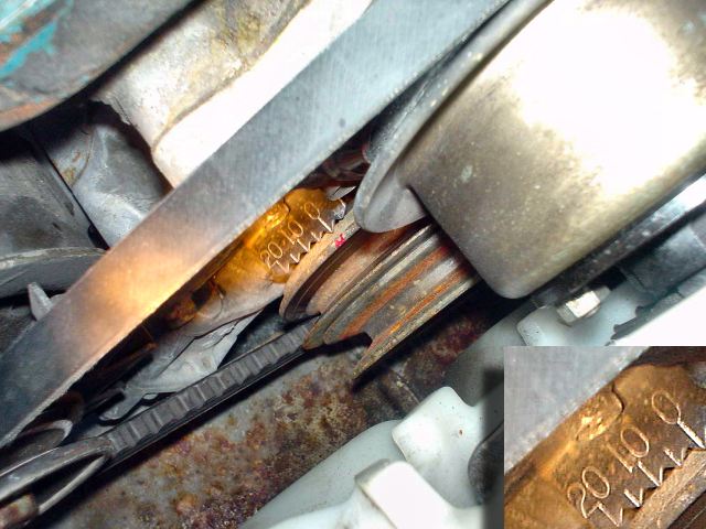
Timing in this photo is at 0° on a 77 280z.