
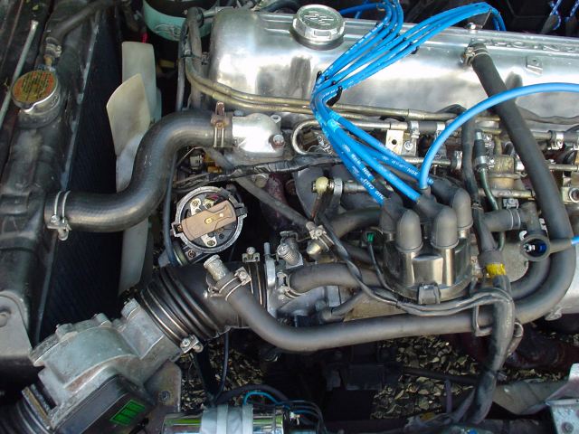
"New" Distributor from early 280zx. It has the E12-80 ignition
"matchbox" circuit integrated.
Two wires from this connect directly to the coil without needing a ballast
resistor.
This results in a more powerful spark as a full 12V (14.7V) is applied to the coil's
primary vs. 6V to 8V when a current limiting ballast is used.
After running this set up for 3 weeks, all I
can say is wow. The higher RPM's are so smooth. Even a club member with 77z
said so thus it is a validated observation.
The spark jumps about 2 to 3 times further when slowly pulling a plug wire.
(With the original set up, I could pull the plug wire only 1cm before
the spark would stop jumping. After the upgrade the spark jumps ~ 2.5cm.
The sound of the spark also changed from a tick to a snap!)
As a reference, I can now hold the plug wire boot so that it's end is exactly
at the sparkplug tip and the spark jumps. I have NGK wires.
Click photo to enlarge!
Remove distributor cap from original
unit and put aside.
Disconnect distributor wires at bulkhead connector and undress wires from
harness back to distributor.
Remove lock bolt at rad side of distributor with 10mm wrench.
Carefully pull distributor out of mount.
Note ground wire and mount.

Disconnect ground. Unbolt and remove mount.
This will expose a gasket.

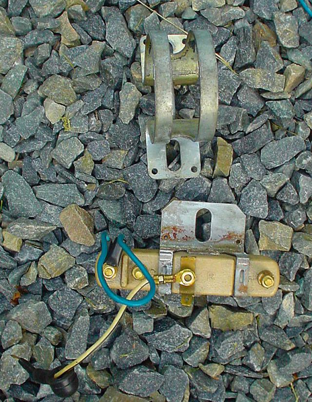
Note difference between 77 mount (left) and 80 (ZX) mount (right).
Install ZX mount. Clean bolts with wire brush and use a contact cleaner to
ensure good electrical connectivity through bolts to block.
Also clean ground wire and attach.

Note: the distributor shaft is keyed (look at the offset of the
corresponding gear spindle) so it is impossible to install the distributor
incorrectly.
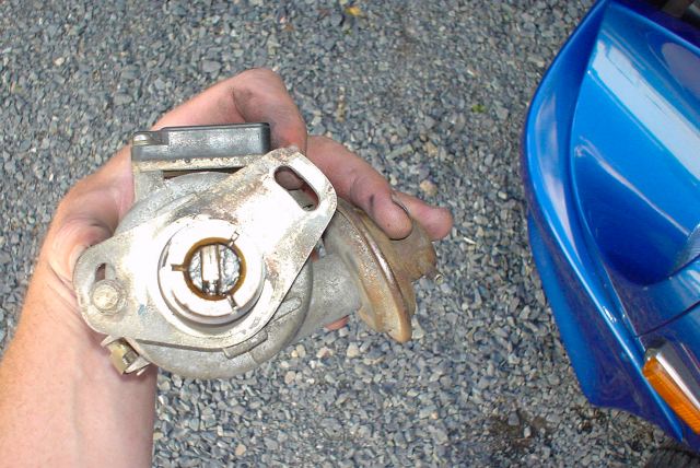
Here is the keyed side of the distributor
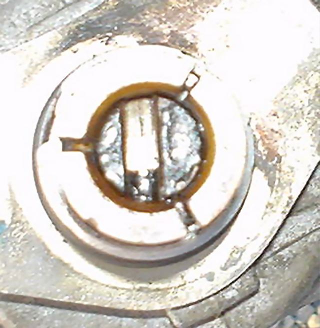
A close up of the offset

Mount the new distributor
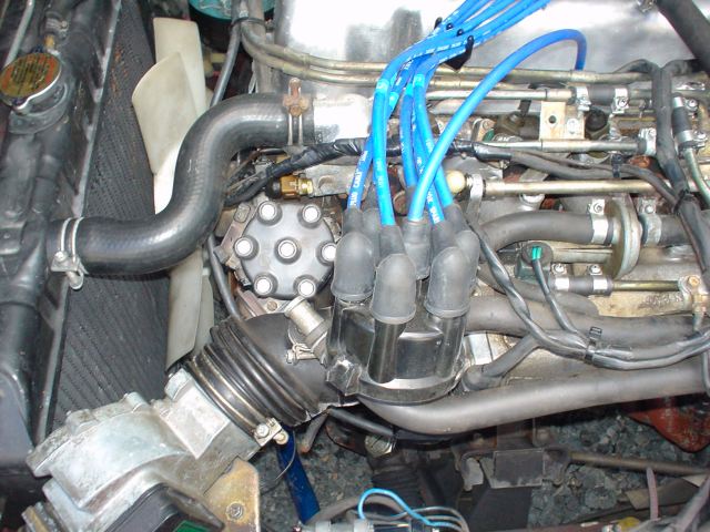
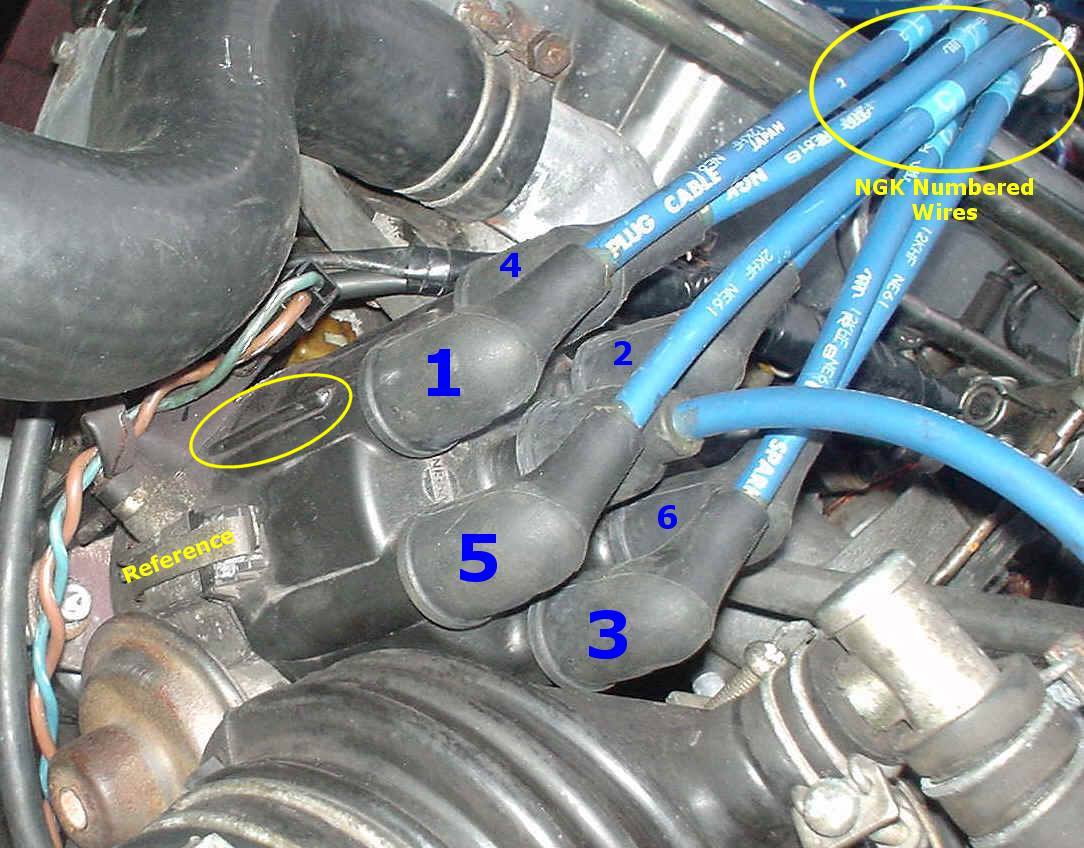
Install cap and transfer plugs
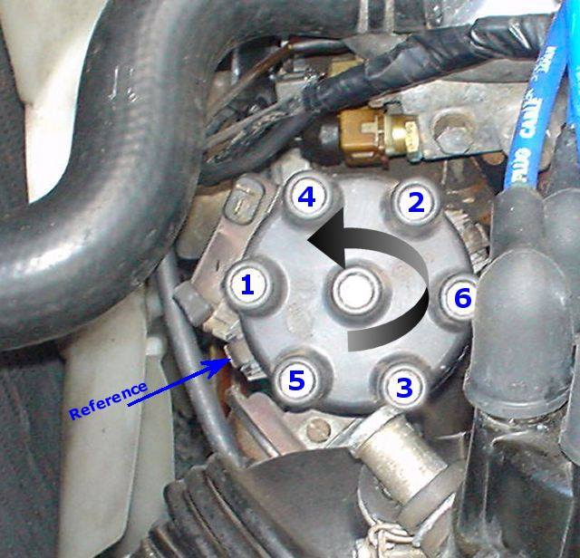
This will help ya!
#1 is closest to the front of the car
FSM showing rotor pointing to #1
Another Reference
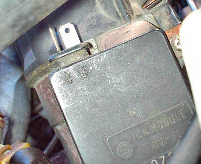
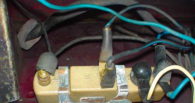
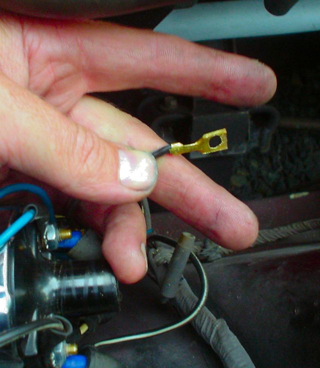
Here is a close up of the new E12-80 ignition unit.
C pin goes to Coil (-Neg coil post)
B pin goes to Bat (+Pos coil post)

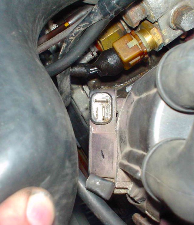
This is the corresponding connector (also removed from the ZX)
I think the oil pressure switch connector is the same format so it is a
possible donor source.
Blue wire goes to C pin.
Brown wire goes to B pin.
Top view of ignition module (tiny fella)
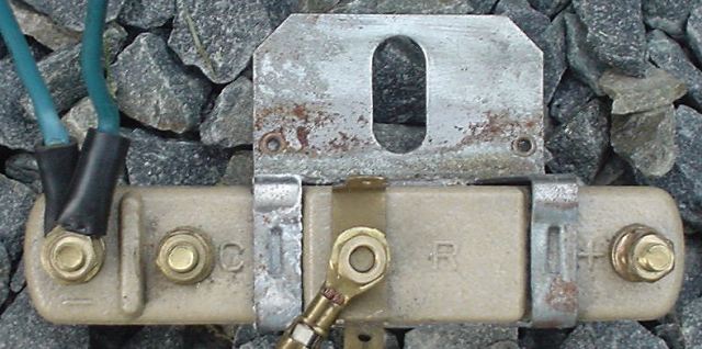
Next step is to see which of the two back w blue striped wires to the
center ballast connector "R" is NOT +12V.
Disconnect both and turn key over to "start" while checking voltage
on each. The one without the voltage goes to a capacitor (aka condenser).
Mark the other one with +12V with red tape.
You can see the two black w blue striped wires on this drawing.
The one to the capacitor (condenser) will be used.
FYI the other black with blue (+12V) goes to pin 15 on the ignition switch
and is only powered when turning over.
This design causes +12V to bypass a portion of the ballast and apply a
stronger spark when starting the engine.
The 12V is removed when the key returns from "Start" to
"On"
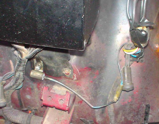
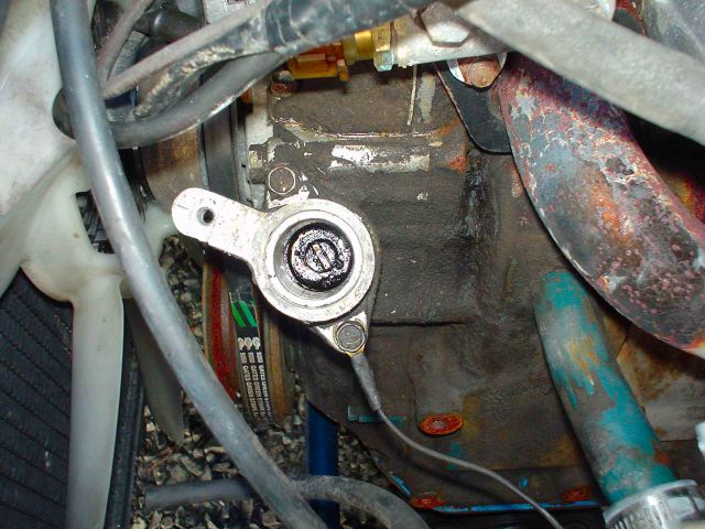
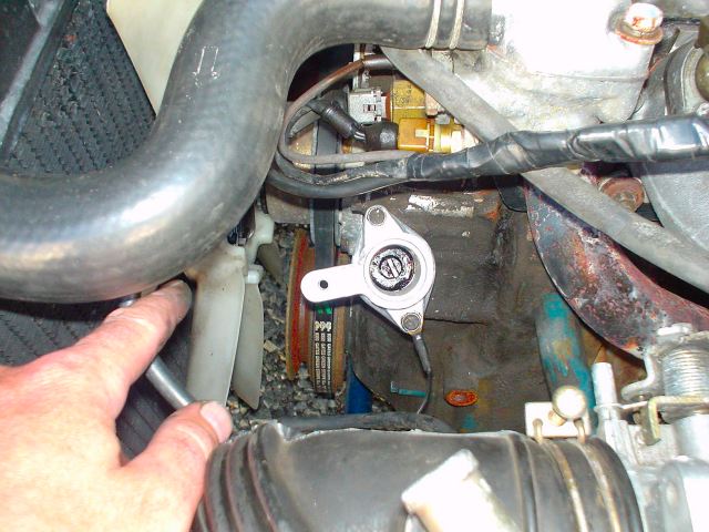
FYI I believe this to be the capacitor mentioned above. I can't recall if
I traced the wire so double check.
It is below the fusible link box on my 77.
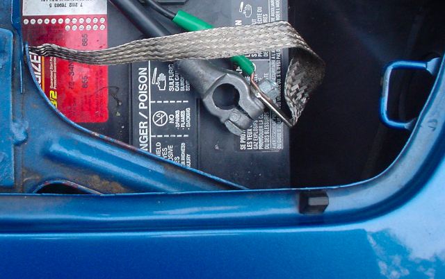
Disconnect the battery.

Here is the end of the wire going to the condenser.
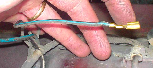
Remove the insulation.
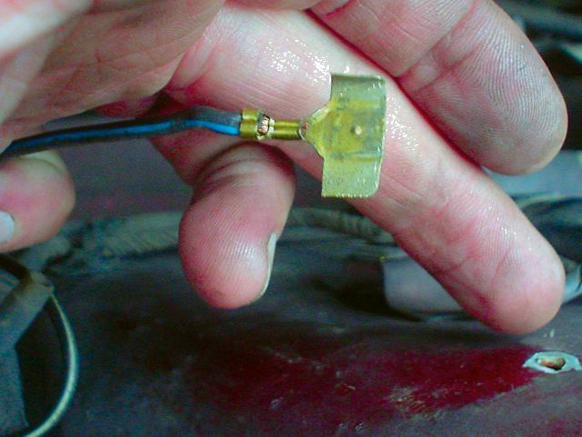
Open connector and flatten with pliers.
Cut off sides and drill hole to allow it to fit on coil's +pos post.

Here is the huge original ignition module on the passenger's kick panel.

Unscrew the wires at the top and remove the unit.
Insulate the wires and "tidy away".
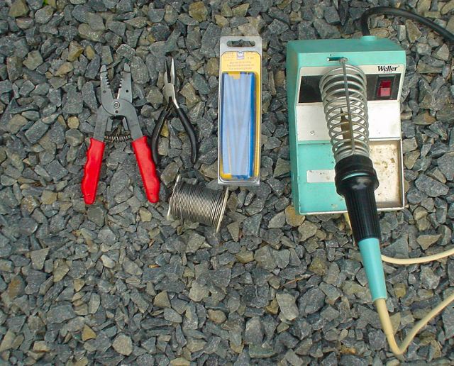
Break out the solder kit to do a good job!
Wire stripper/cutter, pliers, solder, heat shrink, solder iron.
I cut the two wires to the coil on the ZX car at ~ 1 foot from the coil.
This provides nice connectors to connect to my Z's coil posts.
One wire was blue, the other was black with white stripe.
Now is the time to cut the wires to proper length so that the two wires (brown
and blue) from the B & C pins on the ignition can easily reach the coil
when spliced to the 1' end pieces.
Fit heat shrink and twist wires together:
blue to blue
Brown to black with white stripe
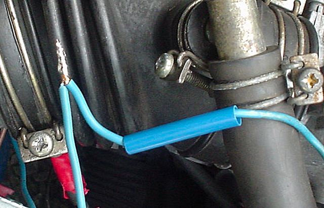
Solder and bend like so.
Slip heat shrink over soldered piece.
Gently heat with hot air gun. Do not overheat or melt heat shrink.

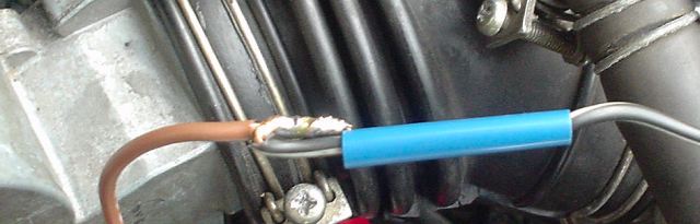
Here is a piece of heat shrink with edge heated with iron to show
shrinkage. (Just like cold water George!).
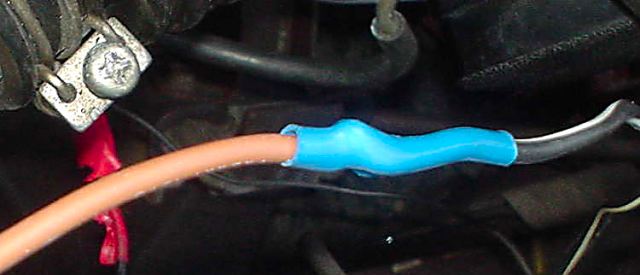
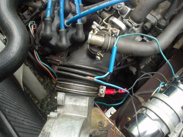
Voila
You can now remove the ballast resistor.
Close up for your inspection
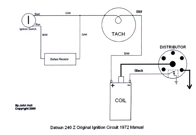
OK here come the schematics:

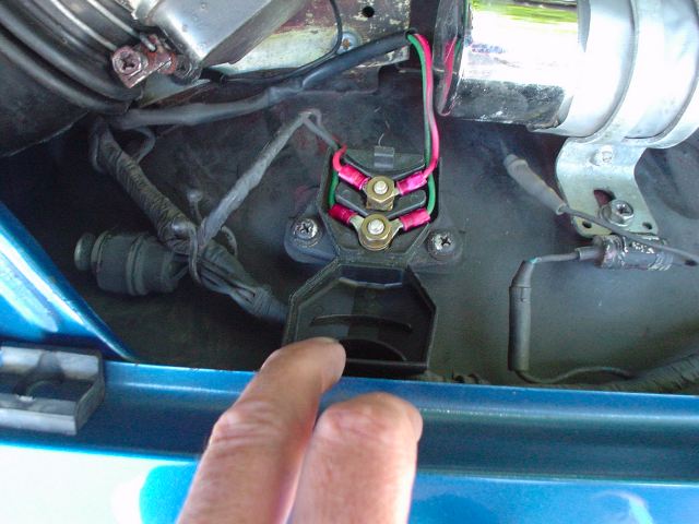
This is the original wiring on my 77 280z (Credits to Wayne Lewis!!!)
Notes:
- Red and Green carry trigger signal to ignition unit. (These will not be used)
- Blue wire to -neg post on ballast block will now go directly to -neg post on coil. (the small blue jumper wire can be discarded). This wire carries the ignition pulse to the ECU's pin 1 and it also goes to the tach after passing through a resistor (see pics above for ECU and resistor). The ECU triggers the injectors from this pulse.
- All wires to original ignition module can be disconnected.
- black and blue +12V to R pin on center of ballast can be insulated and "tidied away". This wire is only HOT when the key is turned to "Start". It goes to pin 15 on the ignition switch (see pic above).
- the other black and blue wire to R pin on ballast is modified to connect to +pos post on coil. This filters coil noise from +12V bus via the condenser.
- +12V black with white stripe wire connected to +pos side of ballast now goes directly to +pos post on coil.
- Blue C wire from new ignition goes to -Neg Coil post
- Brown B wire from new ignition goes to +Pos
Coil post (last 1' is black with white stripe)
This is what it becomes.

You can use this screw to clamp coil in place.
Note: the coil above is a Pertronix flamethrower. It is smaller than the stock
coil. I need a new bracket!
Getting your early Z tach to work with the upgrade (Thanks to www.zhome.com)


Yup, that is the spark! Nice and blue too!
The breakdown field strength for air is often stated to be 30 kV/cm. This is true only for an electrode spacing around 2 cm so this is near 60kV.
The fact the tip is pointed lessens this number. The Pertronix "Flame-Thrower" high performance coil

18mm (I'll measure a stock set up soon... stay tuned)

Here is the measurement on the spark gap device.

Here it is with a typical gap.

Enjoy!